This product is no longer available and has been replaced by: CR1000X. Some accessories, replacement parts, or services may still be available.

| Services Available | |
|---|---|
| Repair | Yes |
| Calibration | Yes |
| Free Support | No |
Overview
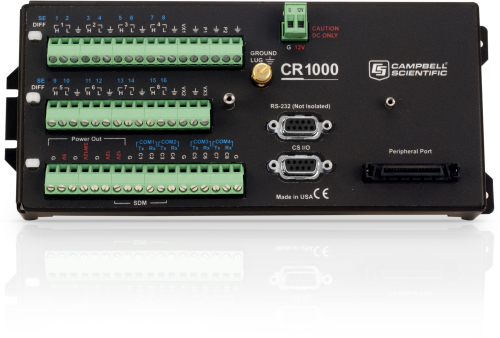
The CR1000 is our most widely used data logger. It can be used in a broad range of measurement and control functions. Rugged enough for extreme conditions and reliable enough for remote environments, it is also robust enough for complex configurations. Used in applications all over the world, it will be a powerful core component for your data-acquisition system.
Read More
Benefits and Features
- Ideal applications include fire weather, mesonet systems, wind profiling, weather stations, air quality, ETo/agriculture, soil moisture, water level/stage, aquaculture, avalanche forecasting, time-domain reflectometry, vehicle testing, SCADA, and water quality
- Serial communications with serial sensors and devices supported via I/O port pairs
- Collects and stores data and controls peripherals as the brain of your system
- Flexible power and communication options make it ideal for remote locations.
- 4-MB memory can be expanded with add-on memory systems.
- Supports PakBus, Modbus, SDI-12, and DNP3 protocols
- Compatible with channel expansion peripherals allowing you to expand your system
- Program with LoggerNet, PC400, or Short Cut to fit your setup
- Communicates via various options: TCP/IP, email, FTP, web server.
- Gas Discharge Tube (GDT) protected inputs
- Battery-backed clock that ensures accurate time is maintained while data logger is disconnected from battery power
- Program and control on site with addition of CR1000KD keyboard and display unit.
- Contains custom ASIC chip that expands pulse count, control port, and serial communications capabilities
Please be advised that Campbell Scientific is nearing discontinuation of the CR1000 Measurement and Control Datalogger. The CR1000 will be available for order through 31 Jan 2020. You will not be able to purchase a CR1000 after this date. Refer to the CR1000 Discontinuation Notice for details.
Images


3D/CAD Files:
Detailed Description
The CR1000 consists of a measurement and control module and a wiring panel. This datalogger uses an external keyboard/display and power supply. Low power consumption allows the CR1000 to operate for extended time periods on a battery recharged with a solar panel—eliminating the need for AC power. The CR1000 suspends execution when primary power drops below 9.6 V, reducing the possibility of inaccurate measurements.
The CR1000's module measures sensors, drives direct communications and telecommunications, reduces data, controls external devices, and stores data and programs in on-board, non-volatile storage. The electronics are RF shielded and glitch protected by the sealed, stainless-steel canister. A battery-backed clock assures accurate timekeeping. The module can simultaneously provide measurement and communication functions. The on-board, BASIC-like programming language supports data processing and analysis routines.
The CR1000WP is a black, anodized aluminum wiring panel that is compatible with all CR1000 modules. The wiring panel includes switchable 12 V, redistributed analog grounds (dispersed among analog channels rather than grouped), unpluggable terminal block for 12 V connections, gas-tube spark gaps, and 12 V supply on pin 8 to power our COM-series phone modems and other peripherals. The control module easily disconnects from the wiring panel allowing field replacement without rewiring the sensors.
Originally, the standard CR1000 had 2 MB of data/program storage, and an optional version, the CR1000-4M, had 4 MB of memory. In September 2007, the standard CR1000 started having 4 MB of memory, making the CR1000-4M obsolete. Dataloggers that have a module with a serial number greater than or equal to 11832 will have a 4 MB memory. The 4 MB dataloggers will also have a sticker on the canister stating “4M Memory”.
Compatibility
Please note: The following shows notable compatibility information. It is not a comprehensive list of all compatible products.
Software
| Product | Compatible | Note |
|---|---|---|
| LoggerNet | Version 3.0 or higher | |
| PC400 | Version 1.2 or higher | |
| RTDAQ | Version 1.0 or higher | |
| Short Cut |
Miscellaneous
| Product | Compatible | Note |
|---|---|---|
| PC200 (retired) | ||
| PCONNECT (retired) | Version 3.1 or higher | |
| PCONNECTCE (retired) | Version 2.0 or higher | |
| SDM-SIO2R | ||
| VISUALWEATHER | Version 2.0 or higher |
Additional Compatibility Information
Sensors
With several channel types, the CR1000 is compatible with nearly every available sensor, including thermocouples, SDI-12 sensors, and 4 to 20 mA sensors (via a terminal input module, such as the CURS100). A custom ASIC chip expands its pulse count, control port, and serial communications capabilities. The CR1000's I/O ports can be paired as transmit and receive, allowing serial communications with serial sensors and devices.
Measurement & Control Peripherals
The CR1000 is compatible with all of our CDMs (requires an SC-CPI), SDMs, multiplexers, vibrating-wire interfaces, terminal input modules, and relays.
Communications
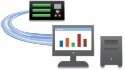
The CR1000 communicates with a PC via direct connect, Ethernet interfaces, multidrop modems, short-haul modems, phone modems (land line, digital cellular, and voice-synthesized), RF telemetry, and satellite transmitters (Argos, Iridium, and Inmarsat).
Data can be viewed on the CR1000KD Keyboard Display, the CD100 Mountable Display with Keyboard, an iOS or Android device (requires LoggerLink), CD295 DataView II Display, or a user-supplied PDA (PConnect or PConnectCE software required).
Compatible external data storage devices are the CFM100, NL115, and SC115.
Enclosures
The CR1000 and its power supply can be housed in any of our standard enclosures.
Power
Any 12 Vdc source can power the CR1000 datalogger. Power supplies commonly used with the CR1000 are the BPALK, PS150, and PS200. The BPALK provides eight non-rechargeable D-cell alkaline batteries with a 7.5 Ah rating at 20°C.
Both the PS150 and PS200 consist of a sealed rechargeable 7 Ah battery and a charging regulator. Their battery should be connected to a charging source (either a wall charger or solar panel). These two power supplies differ in their charging regulator. The PS150 has a standard regulator and the PS200 has a micro-controller-based smart regulator. The PS200's regulator provides two-step constant voltage charging and temperature compensation that optimize battery charging and increases the battery’s life.
Also available are the BP12 and BP24 battery packs, which provide nominal ratings of 12 and 24 Ah, respectively. These batteries should be connected to a regulated charging source (e.g., a CH100 or CH200 connected to a unregulated solar panel or wall charger).
Software
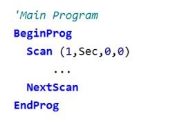
CRBasic, the CR1000's full programming language, supports simple or complex programming and many onboard data reduction processes. Compatible software includes:
- Short Cut
- PC200W
- PC400 (version 1.2 or higher)
- LoggerNet (version 3.0 or higher)
- RTDAQ (version 1.0 or higher)
- PConnect (version 3.1 or higher)
- PConnectCE (version 2.0 or higher)
- VisualWeather (version 2.0 or higher)
Specifications
| -NOTE- | Additional specifications are listed in the CR1000 Specifications Sheet. |
| Operating Temperature Range |
|
| Analog Inputs | 16 single-ended or 8 differential (individually configured) |
| Pulse Counters | 2 |
| Voltage Excitation Terminals | 3 (VX1 to VX3) |
| Communications Ports |
|
| Switched 12 Volt | 1 terminal |
| Digital I/O |
|
| Input Limits | ±5 Vdc |
| Analog Voltage Accuracy | ±(0.06% of reading + offset) at 0° to 40°C |
| ADC | 13-bit |
| Power Requirements | 9.6 to 16 Vdc |
| Real-Time Clock Accuracy | ±3 min. per year (Correction via GPS optional.) |
| Internet Protocols | FTP, HTTP, XML, POP3, SMTP, Telnet, NTCIP, NTP |
| Communication Protocols | PakBus, Modbus, DNP3, SDI-12, SDM |
| Warranty | 3 years |
| Battery-backed SRAM for CPU Usage & Final Storage | 4 MB |
| Idle Current Drain, Average | < 1mA (@ 12 Vdc) |
| Active Current Drain, Average |
|
| Dimensions |
|
| Weight | 1.0 kg (2.1 lb) |
Documents
Technical Papers
- DNP3 Device Profile
- Benefits of Input Reversal and Excitation Reversal for Voltage Measurements
- FTP Streaming
- Preventing and Attacking Measurement Noise Problems
- DNP3 with Campbell Scientific Dataloggers
- Voltage Measurement Accuracy, Self-Calibration, and Ratiometric Measurements
- BACnet to Modbus Protocol Conversion (App. Note: 1M-C)
- Irrometer 950R1-O/950T Radio Network (App.Note: 3MI-F)
- AlphaGUARD Radon Monitor Interfaced with the CR1000 Datalogger
- Serial Sensors: Interfacing with CSI Dataloggers (App. Note Code: 2MI-V)
- CF Card Information (3SM-F)
Compliance
Miscellaneous
Videos & Tutorials
Downloads
CR1000 OS v.32.07 (4.60 MB) 15-05-2024
Execution of this download installs the CR1000 Operating System and Compiler on your computer. It also updates the CR1000 support files for the CRBasic Editor.
Note: This OS has crossed the 2 Meg CR1000 size limit for remote download. The OS must be downloaded to the 2 Meg CR1000 via direct connect with the Device Configuration Utility. All OS download methods are supported by the 4 Meg CR1000.
Upgrading from versions prior to version 28 of the Operating System will reset the datalogger’s CPU drive. This is due to a change in the format of the file system from FAT16 to FAT32. In order for the datalogger to operate correctly, as part of the upgrade, the CPU drive is formatted to FAT32. Any programs stored and running from the CPU drive will be lost. It is not recommended to update the datalogger’s Operating System over a remote connection where program control regulates the communication equipment (turning it on or off, etc.). In these cases, an on-site visit and a backup using DevConfig’s backup utility is necessary to update the datalogger’s Operating System.
Watch the Video Tutorial: Sending an OS to a Local Datalogger.
In all cases where the datalogger is being updated from an Operating System prior to 28, the use of DevConfig’s backup utility is recommended due to the CPU drive being formatted using the new FAT32 format.
Device Configuration Utility v.2.33 (49.6 MB) 07-07-2025
A software utility used to download operating systems and set up Campbell Scientific hardware. Also will update PakBus Graph and the Network Planner if they have been installed previously by another Campbell Scientific software package.
Supported Operating Systems:
Windows 11 or 10 (Both 32 and 64 bit)
Frequently Asked Questions
Number of FAQs related to CR1000: 150
Expand AllCollapse All
-
The data logger’s Status table has a LastSystemScan field that provides this information.
-
For the CR1000 datalogger, the Status table, accessed from the CR1000KD or LoggerNet (version 4) Connect screen, Station Status button, has some statistics that may be useful. Refer to “ProcessTime,” “MaxProcTime,” “MeasureTime,” and “MeasureOps” in Appendix B of the CR1000 Operator’s Manual.
-
The number of data tables that can be defined is limited to 30.
-
The data structure that is used to store data in the data logger CPU memory cannot be downloaded directly. If the memory of a data logger is expanded using a CompactFlash card, the native TOB3 file can be downloaded using the Connect | File Control | Retrieve… menu.
-
The control port maximum output current is 5 mA, but the port is current limited. The voltage will drop to 0 V with an output of 5 mA. Expect no more than 1 mA at 5 Vdc.
-
Use the ModBusServer() instruction in the program editor, and follow the instructions embedded in the Help file.
-
Yes. Each COM port has individual settings and buffers.
-
Use the PreserveVariables() instruction to ensure that all variables reflect the last known value if the data logger experiences power loss.
-
50 Hz rejection is available for analog voltage measurements by setting the Integration parameter.
Case Studies
Tropical volcanic islands are biodiversity hotspots where the Critical Zone (CZ) remains poorly studied. In......read more
Background In 2022, ECR Medio Ambiente assumed the responsibility of overseeing the structural monitoring installation at......read more
Overview The Chauvet-Pont d'Arc and Aven d'Orgnac caves are home to prehistoric treasures of rare artistic......read more
In 2013, a sinkhole appeared next to a historic home in southern Louisiana. Over the......read more
CS110 Electric Field Meter to Recreate the Carnegie Curve of Earth's Fair-Weather Electric Potential Gradient INESC......read more
CS110 Electric Field Meter to Recreate the Carnegie Curve of Earth's Fair-Weather Electric Potential Gradient INESC......read more
The Problem The Lakhta Tower is a building that was completed in 2018, designed for both......read more
The Problem The Lakhta Tower is a building that was completed in 2018, designed for both......read more
Articles and Press Releases
Privacy Policy Update
We've updated our privacy policy. Learn More


