Campbell Core Technology: The Datalogger
by Kevin Rhodes | Updated: 03/21/2018 | Comments: 0
Blog Topics
Area / Application


Product Category


Corporate / News
Search the Blog
Subscribe to the Blog
Get an email when a new article is posted. Choose the topics that interest you most.
Suggest an Article
Is there a topic you would like to learn more about? Let us know.
At Campbell Scientific, we want to help you get the most out of your datalogger that you can. You may have purchased your datalogger to be the core of your data acquisition system without knowing all the things your datalogger can do for you. For example, do you know what all the different terminals, ports, and connection options on your datalogger can be used for? In this blog article, we’ll introduce you to the various parts of a datalogger wiring panel, so you can maximize the benefit you receive from your datalogger. In future blog articles, we’ll take a more in-depth look at some of these parts.
The following illustration depicts the most common parts of a general-purpose datalogger’s wiring panel:
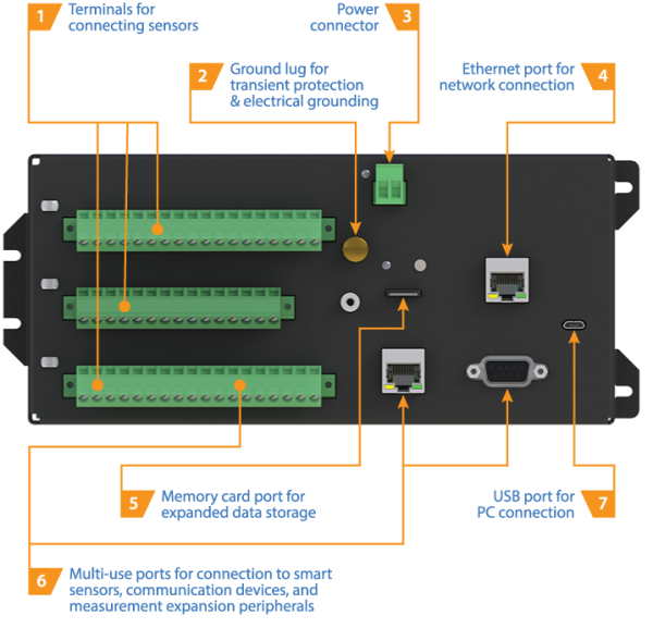
#1 - Sensor Terminals
The wiring panel of a datalogger provides terminals for connecting sensors. These terminals enable the datalogger to measure, communicate with, and power your sensors. Depending on the size and sophistication of the datalogger, the quantity and types of input connections it offers for sensors will vary.
Note: Different sensors produce different types of signal outputs. For your datalogger to interpret the sensor signal, the signal output from the sensor must be compatible with the datalogger input terminal to which it is connected.
Depending on the complexity of your data acquisition system, you may be using a datalogger with some or all of these common sensor terminal types:
- Analog inputs
- Pulse counters
- Switched voltage excitation outputs
- Digital I/O ports
- Communication ports
- Continuous 5 V terminals
- Continuous 12 V terminals
- Switched 12 V terminals
These terminal types are discussed briefly in the following sections. (More details will follow in future blog articles.)
Analog inputs
Analog inputs include both voltage and current inputs. Analog inputs can be configured to make single-ended measurements (measuring the input’s voltage with respect to ground) or differential measurements (measuring the voltage between two inputs).
Sensors that have analog inputs are various, including some models of the following:
- Air temperature and relative humidity sensors
- Mechanical wind direction sensors
- Solar radiation sensors
- Strain gages
- Water level, stage, and flow sensors
Pulse counters
Pulse counters are used by the datalogger to record the number of times that something happens. For example, pulse counters are used to measure switch closures, low-level ac sine waves, or high-frequency pulses. Pulse counters sum the number of counts over each execution (scan), allowing variables such as velocity, flow, and rainfall intensity to be determined.
Pulse counters are often used with any of the following sensors:
- Contact closures
- Flow meters
- Mechanical wind speed sensors
- Tipping bucket rain gages
Switched voltage excitation outputs
Switched voltage excitation outputs provide programmable voltage excitation for resistive bridge measurements. Additionally, these terminals can be configured to supply a regulated 3.3 or 5 Vdc power source to power sensors or toggle control lines.
Digital I/O ports
By default, digital I/O (input and output) ports are configured as binary inputs to perform functions such as detecting status or reading measurement expansion peripherals. In addition, you can individually program each port as a control output to physically control an external device.
Communication ports
Communication ports are used to enable data transfer between your datalogger and various smart sensors. The communication protocols used may be RS-232, RS-485, or SDI-12.
Continuous 5 V terminals
Continuous 5 V terminals are regulated power sources for your sensors and other peripheral devices.
Continuous 12 V terminals
The 12 V terminal is generally used as an unregulated continuous power source for your sensors and other devices.
Switched 12 V terminals
A switched 12 V terminal is used to power your external devices, such as sensors, that only require power during measurements.
You can also use a switched 12 V terminal to switch power to your communication device during scheduled transmission intervals, thereby conserving power.
#2 - Ground Lug
The ground lug connects your datalogger to earth ground. Dataloggers are connected to earth ground to protect them from nearby lightning strikes by shunting transient voltages away from electronics. This also protects from electrostatic discharge and helps assure noise-free analog measurements.
#3 - Power Connector
A power connector provides screw terminals for connecting your datalogger to the wires of its power source. For example, the power connector can be used to connect a 12 V battery. On some dataloggers, you can also connect a 16 to 32 Vdc charging source (such as a power converter or solar panel) to your datalogger.
#4 - Ethernet Port
A datalogger may have an Ethernet port, which is typically used for IP communications with Campbell Scientific software such as LoggerNet and LoggerLink. In addition, it can be used to connect to an Ethernet-enabled camera or sensor.
#5 - Memory Card Port
A memory card port on your datalogger enables you to do the following: save your datalogger internal memory to a card (such as a CompactFlash card or microSD card), easily transport it, and upload your data using a memory card reader. You can upload your data to a computer at an offsite location. Then, your data can be processed for visualization, analysis, sharing, report generation, and permanent storage.
In addition to transferring measurement data, you can use memory cards to transfer your digital camera images, datalogger programs, and datalogger operating systems—without the need for a computer connection.
#6 - Multi-use Ports
Multi-use ports are used to connect your datalogger to smart sensors (that have internal measurement and processing components), communication devices (such as cellular or radio modems), and measurement expansion peripherals.
#7 - USB Port
A micro USB port is primarily used for datalogger programming and testing.
In the absence of an external power supply, the USB connection to a computer also supplies 5 V power to the datalogger, which is adequate for configuration and making some measurements. If Ethernet or wireless data transmission is not feasible, you may need to rely on an onsite transmission option, such as a USB cable connecting your datalogger to a desktop or laptop computer.
Conclusion
We hope this article has introduced you to the various parts of a general-purpose datalogger so that you can get the most out of your datalogger that you can. In future blog articles, we’ll take a more in-depth look at some of the parts of the datalogger wiring panel. In the meantime, let us know if you have any general datalogger wiring panel questions. Please post your questions and comments below.


About the Author
 Kevin Rhodes, now retired, was a Senior Product Manager in the Environmental Market Group at Campbell Scientific, Inc., where he had been employed for more than 20 years. He was instrumental in setting the specifications for several of our data loggers and holds a bachelor's degree in electrical engineering from Utah State University. He contributed to our environmental sustainability efforts by frequently bicycling to and from work, which was of noteworthy distance.
Comments
Please log in or register to comment.