05106-L Wind Monitor, Marine Version
Reliable, Accurate Wind Measurements
Suitable for marine applications
weather applications water applications energy applications gas flux and turbulence applications infrastructure applications soil applications

Overview

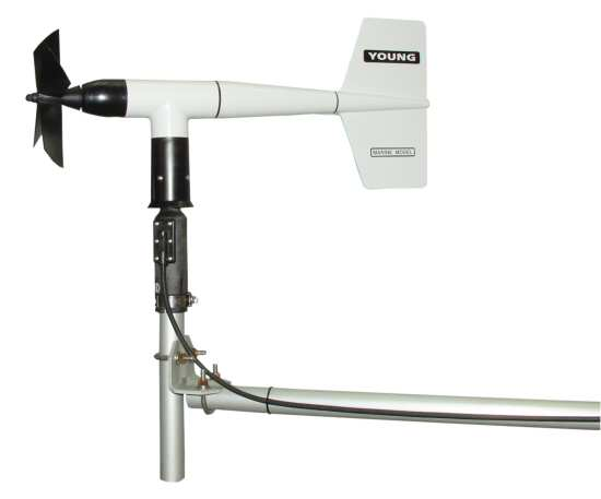
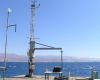
Designed for offshore and marine applications, the 05106 is a lightweight, robust instrument that measures wind speed and direction. Manufactured by R. M. Young, this wind monitor is cabled for use with Campbell Scientific dataloggers.


Read More

Benefits and Features

  • Waterproof bearing lubricant and a sealed, heavy-duty cable pigtail instead of the standard junction box make it more durable at marine and off-shore locations
  • Compatible with most Campbell Scientific data loggers
  • Rugged enough for harsh environments
  • Constructed with thermoplastic material that resists corrosion from sea-air environments and atmospheric pollutants
  • Compatible with the LLAC4 4-channel Low-Level AC-Conversion Module, which increases the number of anemometers one data logger can measure
  • Uses stainless-steel, precision-grade ball bearings for the propeller shaft and vertical shaft bearings
  • Compatible with the CWS900-series interfaces, allowing it to be used in a wireless sensor network

The "-L" on a product model indicates that the cable length is specified at the time of order.


Images


Detailed Description

The 05106 Wind Monitor-MA is made out of rigid UV-stabilized thermoplastic with stainless steel and anodized aluminum fittings. The thermoplastic material resists corrosion from sea air environments and atmospheric pollutants. It uses stainless-steel precision-grade ball bearings for the propeller shaft and vertical shaft bearings.

To make it more durable in offshore and marine applications, the 05106 has waterproof bearing lubricant and a sealed, heavy-duty cable pigtail instead of the standard junction box.

The 05106 measures wind speed with a helicoid-shaped, four-blade propeller. Rotation of the propeller produces an ac sine wave that has a frequency directly proportional to wind speed. The ac signal is induced in a transducer coil by a six-pole magnet mounted on the propeller shaft. The coil resides on the non-rotating central portion of the main mounting assembly, eliminating the need for slip rings and brushes.

Wind direction is sensed by the orientation of the fuselage-shaped sensor body, which is connected to an internal potentiometer. The datalogger applies a known precision excitation voltage to the potentiometer element. The output is an analog voltage signal directly proportional to the azimuth angle.


Specifications

Operating Temperature Range -50° to +50°C (assuming non-riming conditions)
Mounting Pipe Description
  • 34 mm (1.34 in.) OD
  • Standard 1.0-in. IPS schedule 40
Propeller Diameter 18 cm (7.1 in.)
Overall Height 37 cm (14.6 in.)
Overall Length 55 cm (21.7 in.)
Main Housing Diameter 5 cm (2.0 in.)
Weight 1.5 kg (3.2 lb)

Wind Speed

Range 0 to 100 m/s (0 to 224 mph)
Accuracy ±0.3 m/s (0.6 mph) or 1% of reading
Starting Threshold 1.1 m/s (2.4 mph)
Distance Constant 2.7 m (8.9 ft) 63% recovery
Output ac voltage (three pulses per revolution)

90 Hz (1800 rpm) = 8.8 m/s (19.7 mph)
Resolution (0.0980 m s-1)/(scan rate in seconds) or (0.2192 mph)/(scan rate seconds)

Wind Direction

Mechanical Range 0 to 360°
Electrical Range 355° (5° open)
Accuracy ±3°
Starting Threshold 1.1 m/s (2.4 mph) at 10° displacement
Distance Constant 1.3 m (4.3 ft) 50% recovery
Damping Ratio 0.3
Damped Natural Wavelength 7.4 m (24.3 ft)
Undamped Natural Wavelength 7.2 m (23.6 ft)
Output
  • Analog dc voltage from potentiometer (resistance 10 kohm)
  • Linearity is 0.25%.
  • Life expectancy is 50 million revolutions.
Voltage Power switched excitation voltage supplied by data logger

Compatibility

Please note: The following shows notable compatibility information. It is not a comprehensive list of all compatible products.

Dataloggers

Product Compatible Note
21X (retired)
CR10 (retired)
CR1000 (retired)
CR1000X
CR10X (retired)
CR200X (retired)
CR211X (retired)
CR216X (retired)
CR23X (retired)
CR300
CR3000 (retired)
CR310
CR500 (retired) Measurements are typically processed for output with the Wind Vector instruction, which is not present in the CR500.
CR5000 (retired)
CR510 (retired)
CR800 (retired)
CR850 (retired)
CR9000 (retired) Measurements are typically processed for output with the Wind Vector instruction, which is not present in the CR9000.
CR9000X (retired)

Additional Compatibility Information

Mounting

The Wind Monitors can be attached to a CM202, CM204, or CM206 crossarm via a 17953 NU-RAIL fitting or CM220 Right Angle Mounting Bracket. Alternatively, the Wind Monitors can be attached to the top of our stainless-steel tripods via the CM216 Sensor Mounting Kit.

Wind Profile Studies

Wind profile studies measure many wind sensors. For these applications, the LLAC4 4-Channel Low Level AC Conversion Module can be used to increase the number of Wind Monitors measured by one data logger. The LLAC4 allows data logger control ports to read the wind speed sensor’s ac signals instead of using pulse channels. Data loggers compatible with the LLAC4 are the CR200(X) series (ac signal ≤1 kHz only), CR800, CR850, CR1000, CR3000, and CR5000.

Data Logger Considerations

The 05106's propeller uses one pulse count channel on the data logger. Its wind vane requires one single-ended channel and access to an excitation channel (the excitation channel can be shared with other high impedance sensors).

Programming

The 05106's propeller is measured by the PulseCount Instruction in CRBasic and by Instruction 3 (Pulse Count) in Edlog. The wind vane is measured by the BrHalf Instruction in CRBasic and by Instruction 4 (Excite-Delay-SE) in Edlog. The measurements are typically processed for output with the Wind Vector instruction (not present in the CR500 or CR9000 but is present in the CR9000X).


Frequently Asked Questions

Number of FAQs related to 05106-L: 7

Expand AllCollapse All

  1. The short answer is less than 0.01 mA. The wind speed signal requires no power. The wind direction portion of the sensor only uses a maximum of 0.5 mA when excited with 5 Vdc, and then it is only on for 0.016 s for every measurement. When the wind direction is measured every second (typical), the average current drain is less than 0.01 mA.

  2. This depends on the information contained in the calibration sheet:

    • If the calibration sheet contains coefficient information, Campbell Scientific keeps a copy, and a replacement copy can be requested.
    • If the calibration sheet does not contain coefficients, Campbell Scientific does not keep a copy. It may be possible to contact the original manufacturer for a replacement copy.
  3. The information included on a calibration sheet differs with each sensor. For some sensors, the sheet contains coefficients necessary to program a data logger. For other sensors, the calibration sheet is a pass/fail report.

    1. Using Short Cut, click the applicable wind direction sensor in the Selected Sensors list of the Outputs screen.
    2. The two output options enabled are Sample and WindVector. Select WindVector.
    3. The WindVector instruction has output options. Select an option with mean wind direction in it.
  4. Not every sensor has different cable termination options. The options available for a particular sensor can be checked by looking in two places in the Ordering information area of the sensor product page:

    • Model number
    • Cable Termination Options list

    If a sensor is offered in an –ET, –ETM, –LC, –LQ, or –QD version, that option’s availability is reflected in the sensor model number. For example, the 034B is offered as the 034B-ET, 034B-ETM, 034B-LC, 034B-LQ, and 034B-QD.

    All of the other cable termination options, if available, are listed on the Ordering information area of the sensor product page under “Cable Termination Options.” For example, the 034B-L Wind Set is offered with the –CWS, –PT, and –PW options, as shown in the Ordering information area of the 034B-L product page.

    Note: As newer products are added to our inventory, typically, we will list multiple cable termination options under a single sensor model rather than creating multiple model numbers. For example, the HC2S3-L has a –C cable termination option for connecting it to a CS110 instead of offering an HC2S3-LC model. 

  5. Most Campbell Scientific sensors are available as an –L, which indicates a user-specified cable length. If a sensor is listed as an –LX model (where “X” is some other character), that sensor’s cable has a user-specified length, but it terminates with a specific connector for a unique system:

    • An –LC model has a user-specified cable length for connection to an ET107, CS110, or retired Metdata1.
    • An –LQ model has a user-specified cable length for connection to a RAWS-P weather station.

    If a sensor does not have an –L or other –LX designation after the main model number, the sensor has a set cable length. The cable length is listed at the end of the Description field in the product’s Ordering information. For example, the 034B-ET model has a description of “Met One Wind Set for ET Station, 67 inch Cable.” Products with a set cable length terminate, as a default, with pigtails.

    If a cable terminates with a special connector for a unique system, the end of the model number designates which system. For example, the 034B-ET model designates the sensor as a 034B for an ET107 system.

    • –ET models terminate with the connector for an ET107 weather station.
    • –ETM models terminate with the connector for an ET107 weather station, but they also include a special system mounting, which is often convenient when purchasing a replacement part.
    • –QD models terminate with the connector for a RAWS-F Quick Deployment Station.
    • –PW models terminate with the connector for a PWENC or pre-wired system.
  6. Many Campbell Scientific sensors are available with different cable termination options. These options include the following:

    • The –PT (–PT w/Tinned Wires) option is the default option and does not display on the product line as the other options do. The cable terminates in pigtails that connect directly to a datalogger.
    • In the –C (–C w/ET/CS110 Connector) option, the cable terminates in a connector that attaches to a CS110 Electric Field Meter or an ET-series weather station.
    • In the –CWS (–CWS w/CWS900 Connector) option, the cable terminates in a connector that attaches to a CWS900-series interface. Connection to a CWS900-series interface allows the sensor to be used in a wireless sensor network.
    • In the –PW (–PW w/Pre-Wire Connector) option, the cable terminates in a connector that attaches to a prewired enclosure.
    • In the –RQ (–RQ w/RAWS Connector) option, the cable terminates in a connector that attaches to a RAWS-P Permanent Remote Automated Weather Station.

    Note: The availability of cable termination options varies by sensor. For example, sensors may have none, two, or several options to choose from. If a desired option is not listed for a specific sensor, contact Campbell Scientific for assistance.


Case Studies

Delaware: Environmental Observing System
The Delaware Environmental Observing System (DEOS) is a real-time system dedicated to monitoring environmental conditions......read more
Israel: Marine Meteorology on the Red Sea
The meteorological stations at the Interuniversity Institute for Marine Sciences at Eilat (IUI) in Israel......read more
Alaska: Boating Safety
Campbell Scientific's CR10X is the heart of a unique weather station project installed on the......read more

Privacy Policy Update

We've updated our privacy policy.  Learn More