Geotechnical System Design: The Key Considerations
by Andrew Mercer | Updated: 05/05/2026 | Comments: 0
Blog Topics
Area / Application


Product Category


Corporate / News
Search the Blog
Subscribe to the Blog
Get an email when a new article is posted. Choose the topics that interest you most.
Suggest an Article
Is there a topic you would like to learn more about? Let us know.
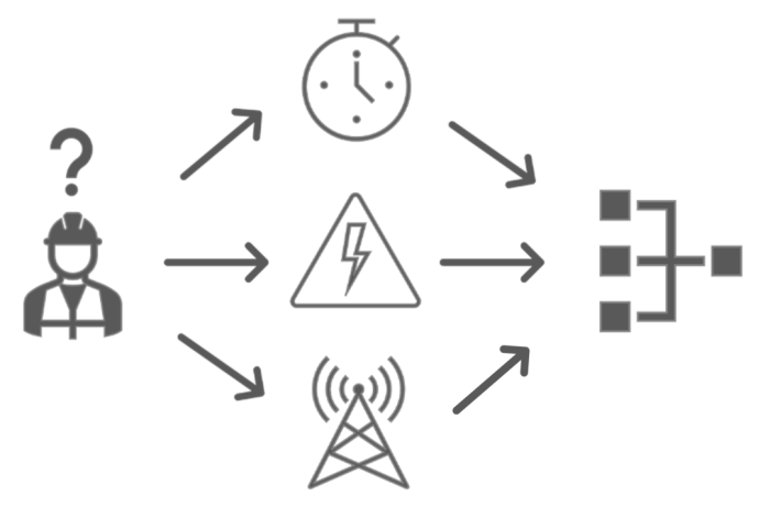
Consider a wall.
If someone asks you to monitor it, that might seem like a simple request. Put up a few tiltmeters, maybe an all-in-one weather station, job done.
But without understanding why the wall needs to be monitored, you can just as easily find yourself missing essential measurements. The asset owner needs reassurance that the wall, its foundations, and the surrounding area are safe for use or continued operations.
Effectively monitoring a parameter is sometimes a difficult challenge. Many variables will impact the success of measuring any specific parameter, and understanding the rationale behind the requirement is crucial to ensure the successful deployment of a monitoring system.
A wall can be considered something simple to measure, and in most cases, it likely is. But to make a point, let’s work through the full range of considerations for monitoring this wall and see where it takes us.
It’s important to remember that instrumentation and monitoring systems for asset measurement—no matter the asset—are ultimately a requirement of safety and longevity.
What Is “The Challenge”?
Every asset comes with its own idiosyncrasies to consider and overcome. That’s one of the things that keeps the geotechnical industry interesting. Imagine how boring it would be if you could thoughtlessly copy and paste every solution from one project to the next.
Now, back to this problematic wall. Why is it problematic? Several reasons could make the wall a concern to the owner:
- It’s sagging or rotating.
- It’s spalling.
- It’s retaining a substrate that requires remediation, such as earthworks or piling.
Understanding the observable issues is a good first step in determining which parameters you need to monitor to validate that the asset is safe and operable. If the concerns aren’t visible, such as foundational failure or ground saturation, appropriate intrusive investigations are generally carried out in the first instance.
For this example, the wall is subject to rotational movements, and the client plans to carry out piling works in close proximity to the asset. That gives us a clear starting point for the parameters we need to measure.
Click the image for a larger version.
What Needs to Be Measured?
Determining what needs to be measured and how are much easier questions to ask than answer. Let’s assume the engineers have already defined the parameters to be measured based on desk study and ground investigation work findings. Our focus then is on the instruments and data acquisition requirements.
Before selecting instruments, you need to consider several factors:
- Fixing details – How will the instrument attach to the asset?
- Is it designed to measure this specific type of asset?
- Can it accommodate the anticipated range of movement (or equivalent parameter) per the structural, geotechnical, or design engineer’s calculations?
The need to measure various parameters is one challenge. Prioritizing them is another, especially when facing budget constraints or tight timeframes. Rationalizing which technology will provide the most cohesive and reliable measurements is essential not only to successfully deliver the project but to stay within budget while delivering a set of measurements both you and your client are confident with.
As our industry evolves, we continue to see experimentation and innovation in monitoring techniques, with varying degrees of success and suitability for different applications. For the sake of this example, we’ll keep it conventional and relatively simple.
With a clear understanding of the asset’s challenges, including the upcoming piling works needing to be near the structure, we can now rationalize the instruments. For this example, we’ll propose instruments with several output types:
- Vibrating wire
- 4–20 mA
- SDI-12
This range of outputs gives us the flexibility to design a comprehensive and agile system with the potential for expandability and redeployment on future projects.
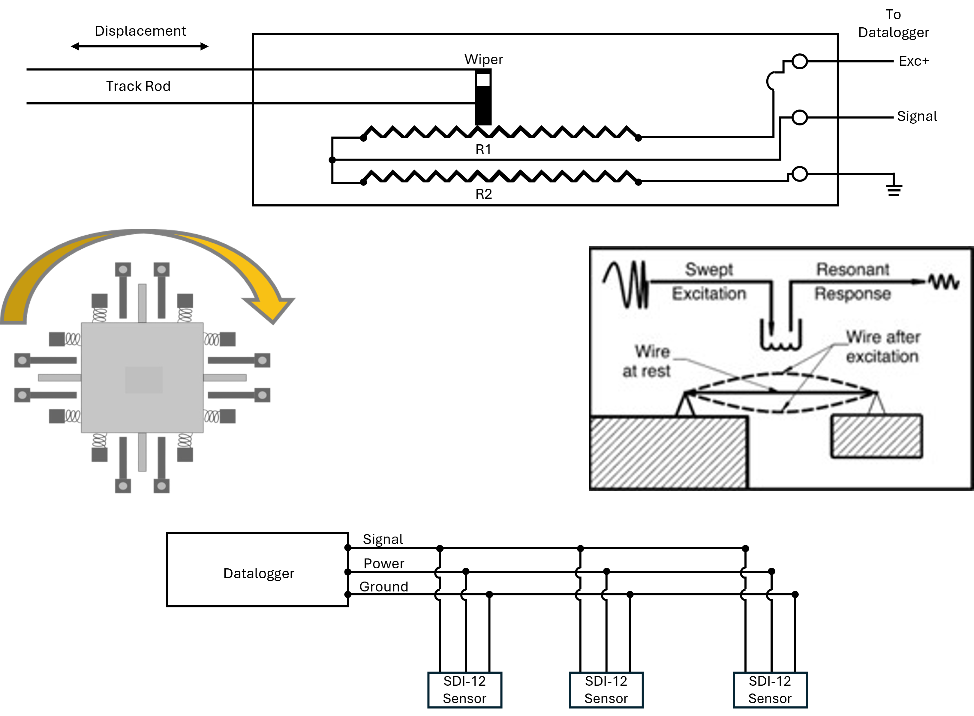
Linear Potentiometer (top), MEMS Accelerometer Mechanism (left), Vibrating Wire Principle (right), SDI-12 Principle (bottom)
Click the image for a larger version.
Measurement Frequency
Measurement frequency—also referred to as sampling frequency, measurement speed, sampling speed, and collection speed—is one of the key determining factors of both the instruments available for a project and the hardware required to measure such instruments.
For this example, we’ve chosen three different output types:
- Analog voltage signal (4–20 mA) – Analog-based instruments generally require consistent excitation (voltage or current) to produce an output.
- Vibrating wire output – This requires an electrical signal to induce resonance, which produces a measurable frequency output based on wire tension.
- SDI-12 output – This type of output is a digital signal with limited measurement frequency potential but capable of addressing multiple instruments via a single cable over long distances while limiting power consumption in static applications.
When selecting the correct instruments, always check the manual for accuracy, resolution, repeatability, and settling time. For vibrating wire instruments, also check the frequency range, as this will determine the fastest permissible measurement frequency.
For most digital outputs (RS-232, RS-422, RS-485, and SDI-12), the maximum measurement frequency is limited, making these instruments well suited for static applications. This limitation exists because digital instruments are polled at set intervals, essentially called upon sequentially to provide a measurement before the data logger moves on to the next instrument and again requests a measurement. That latency adds up and impacts the overall time required to obtain a measurement.
Static Versus Dynamic Measurements
The industry generally recognizes two categories of measurement frequency. These aren’t based on a formal standard but are widely accepted across manufacturers and practitioners:
- Static measurements obtained at intervals greater than one second
- Dynamic measurements obtained at intervals less than one second
For dynamic measurements of oscillating assets or elements, additional considerations apply, particularly the relationship between measurement frequency and the oscillating frequency of the asset or element you’re trying to measure. For more on this, search for “anti-aliasing electrical signals” and the “Nyquist-Shannon theorem.”
For this example, to add a little variety, we’ll measure vibrating wire instruments at one-minute intervals, 4–20 mA instruments at one-minute intervals, and the SDI-12 instrument at ten‑minute intervals.
Communications
In most cases, the requirement is to transmit data off-site or to an on-site control room rather than storing it locally to the data logger. There are various ways to achieve this such as cellular, satellite, Supervisory Control and Data Acquisition (SCADA) integration, and so on. The available options can vary by region. If in doubt, contact your local Campbell Scientific office for advice on available options.
For the purposes of this article, we’ll categorize communications options as either wireless or hardwired.
Wireless Communications
For most applications, a cellular connection is sufficient to transmit recorded measurements off-site to a visualization platform. Keep in mind, though, the variety of cellular modem categories and physical communications between the data logger/gateway and the volume of traffic this connection is expected to handle.
- For instance, when operating with dynamic monitoring systems, a CAT4 modem would generally not be capable of allowing the upload speeds required to avoid a backlog of measurements on the data acquisition system, so we would use a more capable modem such as a CAT12 or 5G where permissible.
- In very remote locations, satellite communications may be necessary.
Both options draw considerable power and should be factored into the power budget, but satellite communications will cost significantly more in the current market. You’ll also need to consider satellite coverage and installation requirements before purchase.
Most countries have some form of cellular network available. Keep in mind the obsolescence of 3G and soon 4G networks. If your system will remain in place for many years, build in some future-proofing. Cellular connections generally cost less and provide wider coverage, including the consistent coverage needed for automated alerting.
For wireless communications between multiple stations or data loggers, radio communications are a common option. The right choice depends on power consumption and data packet size:
- Large data packets or fast transfer (firmware updates, multiple data files) – Wi-Fi or spread spectrum (UHF, VHF) may be preferable.
- Low power consumption and low data transfer – LoRa or LoRaWAN may be preferred.
- Very low power, limited range – Bluetooth may be the best option.
Finding the right fit depends on the application and what you’re trying to achieve from your wireless communications.
Hardwired Communications
There are four main hardwired options, each with their own pros and cons:
- Ethernet
- Serial (RS-232, RS-422, and RS-485)
- CANbus
- Fiber optic
Campbell Scientific has also developed several proprietary communications protocols suited to monitoring projects: PakBus, CPI, EPI, SDI-12, and CS I/O. Reach out to your local Campbell Scientific office to learn more about these protocols.
All the above options—wireless and hardwired—are communications media supported by a variety of protocols, including Modbus, TCP/IP, Ethernet/IP, MQTT/S, HTTP/S, PROFIBUS/PROFINET, BACnet, EtherCAT, and so on.
When determining the best hardwired option, focus on three key considerations: security, addressability, and distance. Each hardwired communications medium has its own limitations in these areas, and understanding your project’s requirements across all three will help determine the best fit.
Power
Now that we know the asset type, parameters, and measurement frequencies, we can consider the system’s power requirements.
When choosing the most appropriate power supply, consider the following:
- System and asset locality
- Measurement frequency
- Communications frequency
- Likelihood of future system expansion
All these factors combined, with some redundancy, means we can continue to obtain measurements in almost any situation.
Location and Solar
The locality is the single biggest determining factor for power supply. A solar panel in the desert will receive more sun hours per day than one installed in a cave. That’s why Campbell Scientific created a free Power Budget Calculator to help with this. The interactive program includes a number of presets and allows you to add your own location and sites.
Note: Temperature has a considerable impact on battery health and longevity, so be sure to include monthly average temperatures for any custom locations you want to consider.
Within the program, you can choose specific hardware (or add your own), set measurement and communications frequencies, and specify the number of days before the system is fully depleted. The calculator will then provide you with the optimal battery capacity (in amp-hours) and solar panel size (in wattage) to run the system at those set intervals.
For solar panels, Monocrystalline (Mono-Si) and Polycrystalline (Poly-Si) are commonly used options in the industry, offering medium-to-high efficiency relative to cost. The installation’s available space and locality will likely determine which panel you choose:
- Limited space – Mono-Si is the better choice due to its higher efficiency per unit area.
- Large space and cost-sensitivity – Poly-Si may be the more economical option.
The following are examples of solar input and discharge graphs.
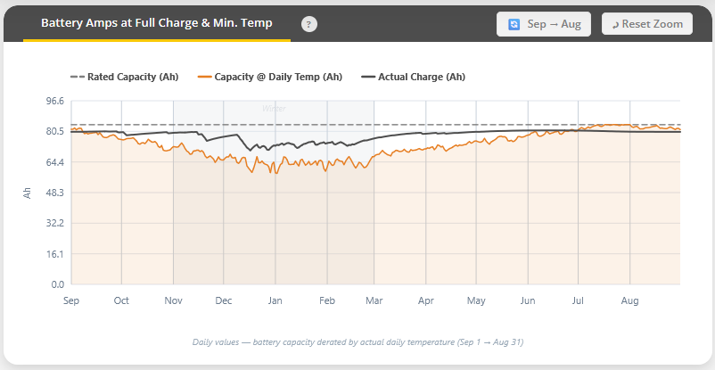
Click the graph for a larger image.
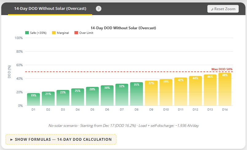
Click the graph for a larger image.
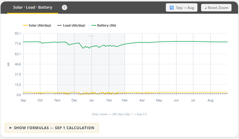
Click the graph for a larger image.
Now that the theoretical calculations are complete and you have a battery and solar panel, optimal installation is next. When installing any solar panel, aim for a south-facing direction in the Northern Hemisphere and a north-facing direction in the Southern Hemisphere, angled at 30 to 40 degrees. A perfect alignment isn’t always possible, but get as close as you can. Before installing, check the surrounding area for potential vegetation and canopy growth. It may not be an issue at the time of installation, but surrounding vegetation could impact panel efficiency during local growing seasons.
Battery Selection
There has been a real push in recent years for better battery technology, which is both a benefit and a potential source of confusion if you’re not deeply familiar with the differences between battery types. The answer to “which battery is best?” generally depends on the application, and it’s rarely straightforward.
When choosing the most appropriate battery, consider the following parameters:
Table 1 – Battery Considerations
| Parameter | Consideration |
|---|---|
| Stability and Drift | Instrumentation systems often require stable and consistent voltages and current. This reduces the potential for false alarms and erroneous measurements. |
| Operating Temperature Range | These systems may be deployed in harsh environments (cold, heat). The battery must operate reliably across that range. |
| Shelf Life and Discharge Rate | Many monitoring systems run intermittently or must last long periods between maintenance. So, a battery capable of holding charge in various environments for an extended period of time is ideal. |
| Reliability and Safety | Battery failure and self-discharge can compromise the monitoring system, so safety, protection, and redundancy are key. |
| Recharge Cycles | Batteries for monitoring systems should not only be rechargeable but also rechargeable with minimum degradation after each discharge. |
| Peak Current/Load | Sometimes a monitoring system draws bursts of current (e.g., communications, boot sequences, alarms). The battery must be able to handle those pulses without excessive voltage drop. |
| Maintenance | Ease of replacement, battery health monitoring, and preventive maintenance potential are ideal. |
| Compliance | For critical instrumentation and monitoring (especially in industrial, safety, or process applications), your battery solution may need to comply with relevant standards or quality requirements (for example, in industries such as oil and gas, IOGP S-740 for batteries used in industrial applications). |
And here’s a breakdown of common battery compositions, along with their pros and cons:
Table 2 – Battery Composition – Pros and Cons
| Composition | Pros | Cons |
|---|---|---|
| Lithium-Ion/Li Polymer |
|
|
| Lithium Iron Phosphate (LiFePO₄) |
|
|
| Lithium Primary (Non-Rechargeable) — e.g. Li-SOCl₂, Li-thionyl chloride, Li-manganese dioxide cells |
|
|
| Nickel-Cadmium (Ni-Cd) or Nickel-Metal Hydride (NiMH) (Rechargeables) |
|
|
| Lead-Acid (Sealed/AGM/Gel) |
|
|
Putting It All Together
With all the building blocks in place, you now have what you need to propose the most suitable system for this problematic wall and to have a productive conversation with the manufacturer who can make it happen. (I know just the company that can help!)
Working through each of these considerations before you approach a manufacturer will lead to a more concise and fruitful discussion around system design. It also makes it easier for both parties to negotiate specific points of disparity, such as channel count, cost, and installation requirements, with solid solutions in hand.
Perhaps most importantly, knowing these considerations allows you to communicate the monitoring system’s requirements to the end client or asset owner with confidence. A strong, well-reasoned proposal makes a real difference when pursuing funding and securing increasingly difficult access to the work area.
For our wall and all the questions that arose, there are a multitude of methods and systems that could fulfill the task. It can feel overwhelming when you’re looking at options from different manufacturers and trying to determine which is best both for you and for the application. It shouldn’t come down to the data logger’s color being the only differentiator.
If the color really is the only differentiator, you’re doing just fine. But if you genuinely aren’t sure which system best fits your application, reach out to a manufacturer and ask for advice.
If you’re provided with a quote in the first email, walk away. You need someone willing to ask questions, learn about your challenge, and tailor a system to your specific requirements.
The probing questions might feel time-consuming or even a little annoying. But there is a reason these questions are asked: to avoid painful lessons that have already been learned the hard way. So, when it comes to installing your monitoring system, you can have confidence in the system’s ability to perform as expected.


About the Author
 Andrew Mercer was a Business Development Manager serving the EMEA Infrastructure market for Campbell Scientific. With more than a decade of instrumentation and monitoring experience as a senior engineer and consultant, Andrew delved into the technical idiosyncrasies of structural health and geotechnical monitoring for both static and dynamic monitoring systems, spending his time solving complex customer challenges to better the industry for the next generation.
Comments
Please log in or register to comment.