This product is no longer available. Some accessories, replacement parts, or services may still be available.
| Services Available |
|---|
Overview
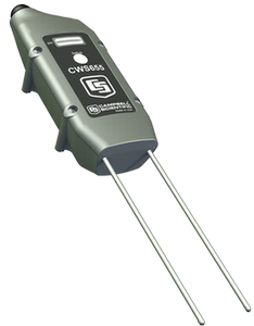
The CWS655A is a wireless version of our CS655 soil water reflectometer. It has 12 cm rods and monitors soil volumetric water content, bulk electrical conductivity, and temperature. This reflectometer has an internal 922 MHz radio that transmits data to a CWB100A Wireless Base Station or to another wireless sensor. The 922 MHz frequency is used in Australia, Israel, and other countries worldwide.
Read More
Benefits and Features
- Versatile sensor—measures dielectric permittivity, bulk electrical conductivity (EC), and soil temperature
- Measurement corrected for effects of soil texture and electrical conductivity
- Internal frequency-hopping, spread spectrum radio provides longer range and less interference
- Battery powered
- A reliable, low maintenance, low power method for making measurements in applications where cabled sensors are impractical or otherwise undesirable
- Transmissions can be routed through up to three other wireless sensors
- Compatible with CR800, CR850, CR1000, and CR3000 data loggers
Images

Detailed Description
The CWS655A has 12-cm rods that insert into the soil. It measures propagation time, signal attenuation, and temperature. Dielectric permittivity, volumetric water content, and bulk electrical conductivity are then derived from these raw values.
Measured signal attenuation is used to correct for the loss effect on reflection detection and thus propagation time measurement. This allows accurate water content measurements in soils with bulk ≤3.7 dS m-1 without performing a soil-specific calibration.
Soil bulk electrical conductivity is also derived from the attenuation measurement. A thermistor in thermal contact with a probe rod near the epoxy surface measures temperature. Horizontal installation of the sensor provides accurate soil temperature measurement at the same depth as the water content measurement. For other orientations, the temperature measurement will be that of the region near the rod entrance into the epoxy body.
Why Wireless?
There are situations when it is desirable to make measurements in locations where the use of cabled sensors is problematic. Protecting cables by running them through conduit or burying them in trenches is time consuming, labor intensive, and sometimes not possible. Local fire codes may preclude the use of certain types of sensor cabling inside of buildings. In some applications measurements need to be made at distances where long cables decrease the quality of the measurement or are too expensive. There are also times when it is important to increase the number of measurements being made but the datalogger does not have enough available channels left for attaching additional sensor cables.
Specifications
| Weather Resistance | IP67 rating for sensor and battery pack (Battery pack must be properly installed. Each sensor is leak tested.) |
| Operating Temperature Range | -25° to +50°C |
| Operating Relative Humidity | 0 to 100% |
| Power Source | 2 AA batteries with a battery life of 1 year assuming sensor samples taken every 10 minutes (Optional solar charging available.) |
| Average Current Drain | 300 μA (with 15-minute polling) |
| Rod Length | 12 cm (4.7 in.) |
| Dimensions | 14.5 x 6 x 4.5 cm (5.7 x 2.4 x 1.77 in.) |
| Weight | 216 g (7.6 oz) |
Measurement Accuracies |
|
| Volumetric Water Content | ±3% VWC typical in mineral soils that have solution electrical conductivity ≤ 10 dS/m. Uses Topps Equation (m3/m3). |
| Relative Dielectric Permittivity |
|
| Bulk Electrical Conductivity | ±(5% of reading + 0.05 dS/m) |
| Soil Temperature | ±0.5°C |
Internal 25 mW FHSS Radio |
|
| Frequency | 920 to 928 MHz |
| Where Used | Australia and New Zealand |
| FHSS Channel | 50 |
| Transmitter Power Output | 25 mW (+14 dBm) |
| Receiver Sensitivity | -110 dBm (0.1% frame error rate) |
| Standby Typical Current Drain | 3 μA |
| Receive Typical Current Drain | 18 mA (full run) |
| Transmit Typical Current Drain | 45 mA |
| Average Operating Current | 15 μA (with 1-second access time) |
| Quality of Service Management | RSSI |
| Additional Features | GFSK modulation, data interleaving, forward error correction, data scrambling, RSSI reporting |
Compatibility
Please note: The following shows notable compatibility information. It is not a comprehensive list of all compatible products.
Documents
Brochures
Miscellaneous


Downloads
Wireless Sensor Planner v.1.7 (30.5 MB) 08-08-2013
The Wireless Sensor Planner is a tool for use with Campbell Scientific wireless sensors. It assists in designing and configuring wireless sensor networks.
Frequently Asked Questions
Number of FAQs related to CWS655A: 18
Expand AllCollapse All
-
Damage to the CWS655 electronics or rods cannot be repaired because these components are potted in epoxy. A faulty or damaged sensor needs to be replaced. For more information, refer to the Repair and Calibration page.
-
No. The equation used to determine volumetric water content in the firmware for the CWS655 is the Topp et al. (1980) equation, which works for a wide range of mineral soils but not for organic soils. In organic soils, the standard equations in the firmware will overestimate water content.
When using a CWS655 in organic soil, it is best to perform a soil-specific calibration. For details on performing a soil-specific calibration, refer to “The Water Content Reflectometer Method for Measuring Volumetric Water Content” section in the CS650/CS655 manual. A linear or quadratic equation that relates period average to volumetric water content will work well.
-
Only the rods of the CWS655A should be buried. The body of the CWS655A was not designed for burial, and Campbell Scientific does not recommend burying it for the following reasons:
- While the body of the CWS655A is underground, the radio signal is diminished, and the soil must be disturbed to replace the batteries.
- Eventually, corrosion of the pins occurs where the battery pack connects. Sometimes moisture gets into the sensor electronics and causes irreparable damage.
If a wireless option is desired for fully buried water content sensors, consider using a CR200X-series datalogger with CS650-L or CS655-L cabled sensors.
-
No. The abrupt permittivity change at the interface of air and saturated soil causes a different period average response than would occur with the more gradual permittivity change found when the sensor rods are completely inserted in the soil.
For example, if a CWS655 was inserted halfway into a saturated soil with a volumetric water content of 0.4, the probe would provide a different period average and permittivity reading than if the probe was fully inserted into the same soil when it had a volumetric water content of 0.2.
-
There are three reasons that NAN values are reported:
- A communication issue exists between the CWS655x sensor and the CWB100x base station.
- Soil conditions are in an out-of-bounds range beyond the sensor’s calibration.
- A hardware issue exists within the sensor electronics.
The CWS655-series sensors have several logical tests built into their firmware to ensure that the sensors do not report a number that is known to be erroneous. Erroneous readings are either outside the sensor’s operational limits or outside of published accuracy specifications.
A reported value of NAN does not necessarily mean that there is a problem with the sensor hardware. The conditions outlined below can lead to a value of NAN for volumetric water content.
Radio communication issue
When the CWB100 base station is about to poll a wireless sensor, it first populates the variable array specified in the data logger program with a NAN value for each field. Then, when a successful transmission of sensor data is received, those NAN values are overwritten with valid data. If the transmission is unsuccessful, all of the values for that sensor remain as NAN. This makes it easier to tell when there is an issue. Possible causes of a radio communication issue include:
- The sensor is not powered. Press the Setup button on the back of the sensor, and count the number of blue LED flashes on the front of the sensor. Four flashes indicate a fully charged battery, whereas one flash indicates a low battery that needs replacement or recharging. If there are no blue flashes, this indicates that the battery pack is not working at all and likely needs to be checked for damage.
- The wireless sensor has not been detected by the base station. Press the Setup button on the back of the sensor, and count the number of red LED flashes on the front of the sensor. The number of red flashes indicates how many hops the sensor must take to reach the CWB100 base station. One to four red flashes indicate that the sensor has been discovered by the base station. If there are no red flashes, this indicates that the wireless sensor has not been discovered by the base station. Hold the Setup button for eight seconds to force a search for the base station. After eight seconds, the blue LED flashes once per second until the sensor and base station have synchronized or until an unsuccessful search has timed out (approximately 8 minutes).
- If the CWB100 base station cannot discover the CWS655, use DevConfig with the A205 interface to connect to the CWS655 and check its settings as described in the Wireless Sensor Network Instruction Manual. Select Connect in DevConfig, and press the Setup button on the back of the sensor.
- Check that the radio address of the CWS655 is present in the Radio Address field. If that field is blank, the sensor has a damaged radio module and is unable to detect its own radio. The sensor will need to be replaced.
- Check that the radio address for the CWB100 base station is correctly entered in the Base Station Address field. The base station address is printed on a sticker on the CWB100. The CWS655 needs to have this address entered so that it will respond when the base station tries to discover it.
- Select the Settings Editor tab and scroll down to Measurements. This will query the sensor every 5 seconds and display readings for volumetric water content (VWC), bulk electrical conductivity (EC), temperature (Ts), apparent bulk permittivity (Pe), voltage ratio (AR), period, internal sensor temperature (Ti), and battery voltage (BV). Certain soil conditions may cause NAN values in the VWC, EC, and/or Pe fields, but a working sensor always reports Ts, AR, period, Ti, and BV. If any of those fields report NAN, the sensor is damaged.
- If the DevConfig settings are all correct but the CWB100 base station does not discover the CWS655 sensor, then the radio signal strength (RSSI) should be checked. Common causes of failed transmission between the CWS655 and the CWB100 base station include the following: poor line of sight between the sensor and base station, too much distance, radio interference from other sources, and the absorption of RF energy by water or leaves. Sometimes these issues may be resolved by adding one or more wireless sensors to the system to serve as repeaters.
Permittivity is greater than 42
The CWS655 calculates real apparent bulk permittivity of soil and then uses the Topp et al. (1980) equation to convert permittivity to volumetric water content. A permittivity value of 42 is the upper limit for making that conversion. This is equivalent to a volumetric water content of 0.52.
If the reported value for VWC is NAN but there is a numerical value for Pe, then volumetric water content numbers higher than 0.52 may be calculated by applying the Topp et al. (1980) equation or another chosen equation to the permittivity reading. This may be done in the data logger program or in post-processing software, such as a spreadsheet. Note that the Topp et al. (1980) equation is typically held to be valid for water content values between 0 and 0.55 m3 m-3.
Permittivity value is NAN
Because volumetric water content is calculated from the permittivity reading, conditions that cause the sensor to report NAN for permittivity will give the same value for volumetric water content.
-
To get accurate water content readings, a soil-specific calibration is probably required if any of the following are true:
- The soil has more than 5% organic matter content.
- The soil has more than 20% clay content.
- The soil is derived from volcanic parent material.
- The soil has porosity greater than 0.5.
For details on performing a soil-specific calibration, refer to “The Water Content Reflectometer Method for Measuring Volumetric Water Content” section in the CS650/CS655 manual.
Some users have obtained good results by applying a linear correction to the square root of reported permittivity before applying the Topp et al. (1980) equation. The linear correction is obtained by taking readings in saturated and dry soil and using volumetric water content measurements obtained from oven-dried soil samples to estimate actual permittivity.
-
The CWS655 works best when the rods are inserted into the soil as parallel to each other as possible. To make parallel pilot holes before installation, use the CS650G Rod Insertion Guide Tool. Minor deflection of a rod during insertion, such as when it contacts a small stone or root, may not affect the readings significantly. Major deflections, however, may cause the CWS655 to operate outside of published accuracy specifications, as well as to damage the sensor housing.
-
A thermistor is encased in the epoxy head of the sensor next to one of the stainless-steel rods. This provides a point measurement of temperature at the soil surface. The temperature measurement is not averaged over the length of the sensor rods.
-
If information is available on soil texture, organic matter content, and electrical conductivity (EC) from soil surveys or lab testing of the soil, it should be possible to tell if the soil conditions fall outside the range of operation of the CWS655. Without this information, an educated guess can be made based on soil texture, climate, and management:
- Mineral soils work well with a CWS655 if the EC at saturation is below 3.04 dS/m.
- If the soil is located in an arid or semiarid region, it may have high EC.
- If the soil is frequently fertilized or irrigated with water that has higher EC, it may have high EC.
- If the climate provides enough rain to flush accumulated salts below the root zone, the EC is expected to be low and suitable for a CWS655.
- Organic or artificial soils typically have high surface electrical conductivity and may become out-of-bounds if they receive significant fertilizer or water with high EC.
-
No. It is not possible to disable the logical tests in the firmware. If soil conditions cause frequent NAN values, it may be possible to perform a soil-specific calibration that will provide good results.
If permittivity is reported but the volumetric water content value is NAN, Campbell Scientific recommends a soil-specific calibration that converts permittivity to water content. This will take advantage of the bulk electrical conductivity correction that occurs in the firmware.
If both permittivity and volumetric water content have NAN values, it may be possible to perform a calibration that converts period average directly to volumetric water content.
For details on performing a soil-specific calibration, refer to “The Water Content Reflectometer Method for Measuring Volumetric Water Content” section in the CS650/CS655 manual. After a soil-specific equation is determined, it may be programmed into the data logger program or used in a spreadsheet to calculate the soil water content.
Privacy Policy Update
We've updated our privacy policy. Learn More